Know This Before You Buy Rubber Spider for Coupling
September 8, 2025
Why Importers Prefer MT Couplings from India
September 22, 2025
Choosing the right jaw coupling size isn't just a technical detail—it's the base of your machinery's reliability and performance. Selecting the wrong size can lead to premature wear, harmful failure, and costly operational downtime. The key is to move beyond simple shaft size matching and implement a more systematic approach.
So, how do you select the correct jaw coupling size?
The right jaw coupling size is determined by calculating your application's design torque—which is the nominal torque multiplied by the appropriate service factor—and then choosing a coupling from a manufacturer's chart whose torque rating and bore capacity meet or exceed your requirements.
At Manglam Engineers, we've spent decades helping OEMs, EPC contractors, and industrial leaders master the science of mechanical power transmission. This guide turns our expertise into a simple, step-by-step process to ensure you get the perfect fit every time. We'll cover everything from torque calculations to selecting the right spider material, empowering you to make an informed decision.
What Exactly Is a Jaw Coupling?
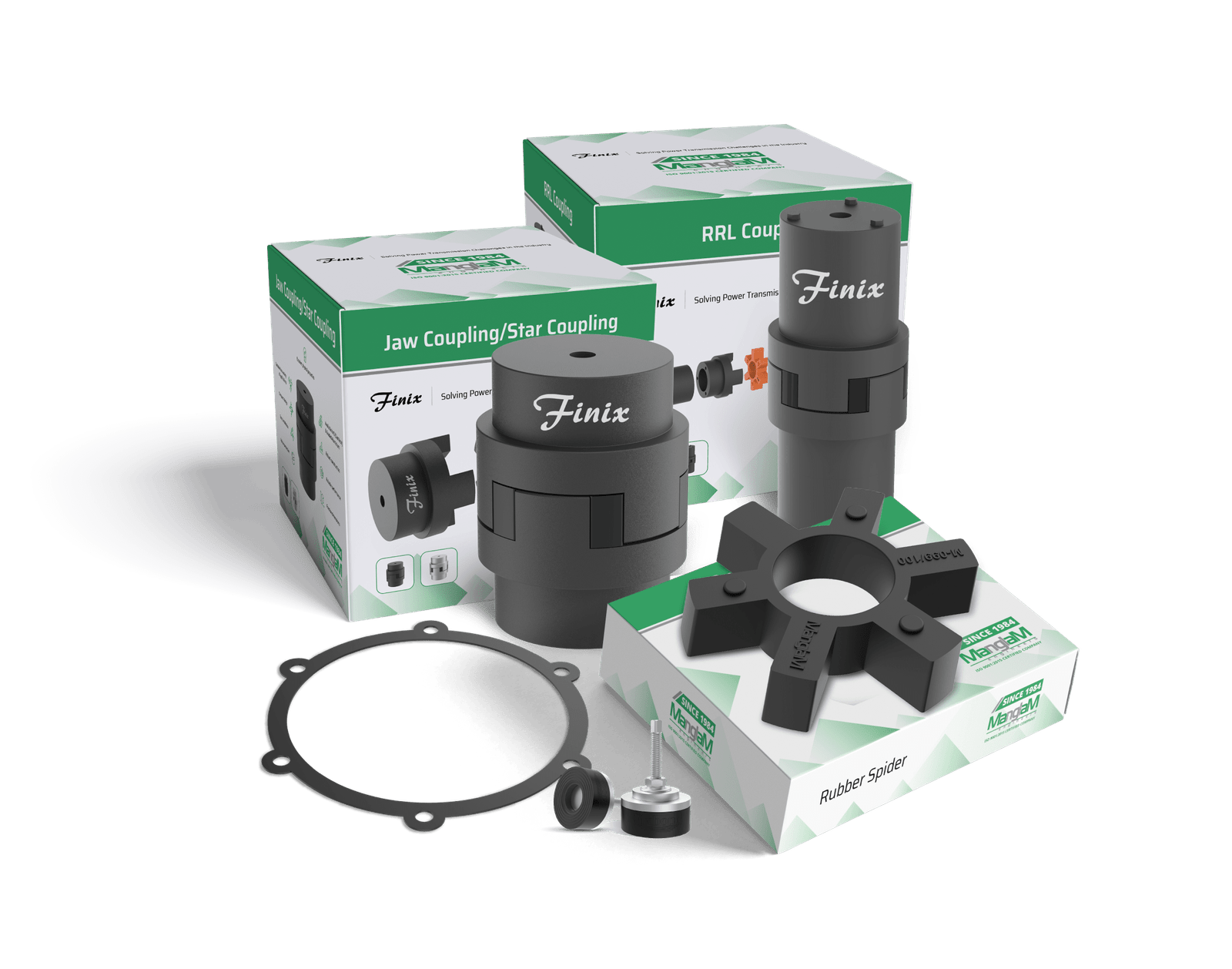
A jaw coupling is a type of flexible power transmission coupling designed to connect two shafts and transmit torque while dealing with minor misalignment. Its simple, three-part construction is its greatest strength, consisting of two metal hubs and a flexible elastomer insert, commonly known as a "spider."
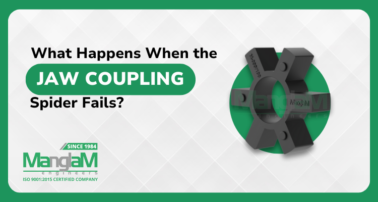
The hubs have interlocking "jaws" that fit into the sides of the spider. As the driving shaft rotates, torque is transmitted through the hubs to the spider, and then from the spider to the driven hub. This design makes it a secure coupling, as the jaws of the hubs will still engage even if the spider fails, preventing a complete loss of power.
Why Is Jaw Coupling Sizing So Important?
Getting the jaw coupling size right is fundamental to the health of your entire mechanical system. An incorrectly sized coupling acts as a weak link, leading to a range of problems that can pause production and raise maintenance budgets.
- Undersized Couplings: A coupling with a torque rating too low for the application will experience rapid degradation of its spider and may even cause the metal hubs to fracture under load. This is the most common cause of premature failure.
- Oversized Couplings: While visually safer, an oversized coupling is more expensive, heavier, and adds unnecessary mass to the rotating system. This can reduce efficiency and may not provide the intended level of flexibility or vibration damping.
- System Integrity: Correct sizing ensures smooth power transmission, protects connected equipment like motors and gearboxes from shock loads, and maximizes the operational lifespan of all components.
Manglam Engineers – Your Go-to Source For Long-lasting, High-performance Jaw Coupling.
How Do You Calculate Jaw Coupling Size? A 5-Step Guide
Follow this proven, five-step method to accurately choose the right jaw coupling for your specific application. This process ensures your account for all critical operational variables.
Step 1: Determine the Application's Nominal Torque
First, you need to calculate the basic torque requirement of your system. This is known as the nominal torque (T_N). The formula depends on the units you're using for power and speed.
For power in kilowatts (kW) and speed in revolutions per minute (RPM):
Torque (Nm) = (Power (kW) * 9550) / Speed (RPM)
For power in horsepower (HP) and speed in revolutions per minute (RPM):
Torque (in-lbs) = (Power (HP) * 63025) / Speed (RPM)
Step 2: Apply the Correct Service Factor (SF)
No machine operates in a perfect world. The Service Factor (SF) is a powerful multiplier that accounts for real-world operating conditions like shock loads, duration of operation, and the type of driving and driven machinery. Ignoring the SF is a direct path to undersizing.
Consult a service factor chart, like the example below, provided by manufacturers.
| Driving Unit | Driven Machine Load Characteristic Uniform (e.g., Centrifugal Pumps) |
|---|---|
| Electric Motor | 1.0 |
| Engine (4+ Cylinders) | 1.25 |
| Engine (<4 Cylinders) | 1.5 |
Example (cont.): Our 15 HP motor is driving a loaded belt conveyor (a moderate shock application). According to the chart, the Service Factor (SF) is 1.5.
Step 3: Calculate the Final Design Torque
Now, combine your nominal torque and service factor to find the design torque (T_D). This is the value you will use to select the coupling.
DesignTorque(TD )=NominalTorque(TN )×ServiceFactor(SF)
Step 4: Select the Coupling from a Jaw Coupling Chart
With your design torque calculated, you can now consult a manufacturer's jaw coupling sizing guide or specification chart. Your goal is to find a coupling model whose nominal torque rating is greater than or equal to your calculated design torque.
Here is a simplified example of what a sizing chart looks like:
| Coupling Model | Nominal Torque Rating (in-lbs) | Max Speed (RPM) | Max Bore (inch) |
|---|---|---|---|
| ME-50 | 550 | 6000 | 1.125 |
| ME-65 | 1100 | 5500 | 1.375 |
| ME-80 | 2200 | 4500 | 1.625 |
| ME-90 | 3500 | 4000 | 2.125 |
Example (cont.): Our design torque is 945.38 in-lbs. Looking at the chart, the ME-50 model is too small (550 < 945.38). The ME-65 model, with a rating of 1100 in-lbs, is the correct choice as it's the first size that exceeds our requirement.
Step 5: Verify Shaft and Bore Compatibility
The final, critical check is to ensure the selected coupling can accommodate your machine's shafts. The maximum bore diameter listed for the coupling model must be larger than both your driver and driven shaft diameters. Also, confirm the keyway specifications to ensure a secure and positive power transmission.
Example (cont.): The ME-65 model has a max bore of 1.375 inches. If both the motor and conveyor shafts are 1.25 inches, this coupling is a perfect fit.
What Other Factors Influence Jaw Coupling Selection?
While torque and bore size are primary, a truly powerful selection considers the complete operational environment. These secondary factors ensure long-term reliability.
Shaft Misalignment
Every system has some degree of misalignment. Jaw couplings are excellent at accommodating it, but the type and size matter.
- Angular: Shafts are at an angle to each other.
- Parallel: Shafts are parallel but offset.
- Axial: Shafts move closer together or further apart.
Check the manufacturer's data sheet for the coupling's specific misalignment capabilities to ensure it can handle your system's conditions.
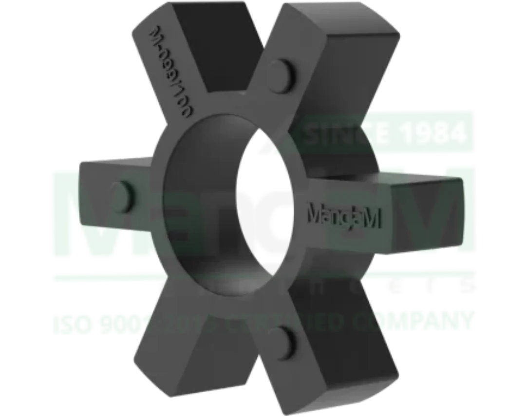
Spider (Elastomer) Material
The spider is the heart of the coupling, and its material dictates performance characteristics like vibration damping, chemical resistance, and operating temperature.
| Spider Material | Hardness (Shore A) | Temp. Range | Dampening | Best For |
|---|---|---|---|---|
| NBR (Buna-N) | 80A | -40°C to 100°C | Excellent | Standard industrial use, good oil resistance. |
| Urethane | 90–95A | -30°C to 70°C | Good | Higher torque, better chemical resistance. |
| Hytrel® | 98A (or higher) | -50°C to 120°C | Moderate | High torque, high temperature, excellent durability. |
| Bronze | N/A | Very High | Low | Slow-speed, high-torque applications where lubrication is possible. |
Operating Speed and Environment
Always cross-reference your system's max RPM with the coupling's speed rating. Exceeding this can cause the coupling to vibrate excessively or fly apart, creating a major safety problem. Additionally, consider environmental factors like chemical exposure or extreme temperatures when selecting both the hub and spider materials.
Jaw Coupling
What Are Some Common Jaw Coupling Sizing Mistakes?
Avoiding these common errors can save you significant time and money.
- Ignoring Service Factors: Trusting only on nominal torque is the #1 mistake. It leads to selecting a coupling that isn't strong enough for the application's real-world dynamic loads.
- Using Shaft Size Alone: Simply picking a coupling with a bore that fits your shaft ignores the critical torque and speed requirements, leading to a mismatched and unreliable component.
- Mismatching the Spider: Selecting a standard NBR spider for a high-temperature or chemical-heavy environment will result in rapid failure. Always match the elastomer to the environment.
- Exceeding Misalignment Limits: Pushing a coupling beyond its stated misalignment capabilities will drastically reduce the life of the spider and put excessive stress on connected bearings and seals.
How Do Jaw Couplings Compare to Other Options?
Your Partner in Precision: Manglam Engineers
Selecting the correct jaw coupling size is a straightforward process when you have the right data and expertise. By following the steps of calculating design torque, consulting manufacturer charts, and considering all environmental factors, you can ensure your machinery runs smoothly and reliably.
At Manglam Engineers, we do more than just supply parts; we provide solutions. Our extensive inventory of high-quality jaw couplings, along with other essential components like Normex Type, Rotex Type, and Chain Couplings, is backed by a team of engineers ready to assist you. We are your trusted jaw coupling manufacturer and supplier, dedicated to precision and performance.
- Need help with your calculations? Consult our engineering experts today for a personalized recommendation.
- Have a unique or demanding application? Request a free quote and let us engineer the optimal solution for you.
Frequently Asked Questions (FAQ)

Dhaval Jani
Managing Director at Manglam Engineers
Dhaval Jani is the Managing Director of Manglam Engineers , a trusted manufacturer of transmission couplings and rubber parts. With a background in mechanical engineering and extensive industry experience, he leads the company’s focus on product innovation, manufacturing excellence, and global business growth.