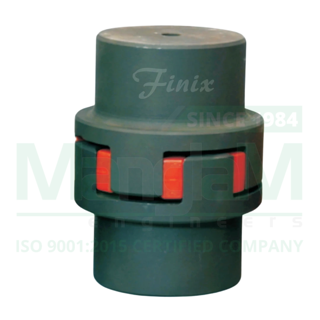
GR Couplings are a three-piece assembly consisting of two hubs made from Aluminium Alloy, Cast Iron, or Steel, and one Special Grade Polyurethane Spider. These components are assembled coaxially to form the complete GR Coupling. Once assembled, the coupling offers flexibility, positive motion transmission, and a fail-safe power transfer mechanism. The Polyurethane Spider acts as a buffer between the two metallic hubs, preventing direct contact. This separation helps in providing electrical and frequency isolation between the connected driving and driven units.
Working Principle of GR Coupling
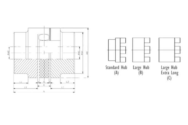
| Dimensional Details - GR Coupling | ||||||||||||||
|---|---|---|---|---|---|---|---|---|---|---|---|---|---|---|
| Size PUFlex GR | Bore Sizes (mm) | Overall Dimensions | ||||||||||||
| Minimum | Maximum | Outer Dia. | Hub Dia. | Spider I.D. | Total Length Std./Large Hub | Total Length Extra Long Hub | Hub Length | Hub Length | Hub Length | Space Between Hubs | Spider Width | Isolation Gap | ||
| Std. Hub | Large Hub | |||||||||||||
| d1 | d2 | d2 | D | D1 | d3 | L | L | Std. L1 | Extra Long L1 | L2 | E | b | a | |
| MGR 19 | 6 | 19 | 24 | 41 | 32 | 18 | 66 | 90 | 25 | 37 | 20 | 16 | 12 | 2 |
| MGR 24 | 9 | 24 | 28 | 56 | 40 | 27 | 78 | 118 | 30 | 50 | 24 | 18 | 14 | 2 |
| MGR 28 | 10 | 28 | 38 | 66 | 48 | 30 | 90 | 140 | 35 | 60 | 28 | 20 | 15 | 2.5 |
| MGR 38 | 12 | 38 | 48 | 80 | 66 | 38 | 114 | 164 | 45 | 70 | 37 | 24 | 18 | 3 |
| MGR 42 | 14 | 42 | 55 | 95 | 75 | 45 | 126 | 176 | 50 | 75 | 40 | 26 | 20 | 3 |
| MGR 48 | 15 | 48 | 62 | 105 | 85 | 51 | 140 | 188 | 56 | 80 | 45 | 28 | 21 | 3.5 |
| MGR 55 | 20 | 55 | 74 | 120 | 98 | 60 | 160 | 210 | 65 | 90 | 52 | 30 | 22 | 4 |
| MGR 65 | 22 | 65 | 80 | 135 | 115 | 68 | 185 | 235 | 75 | 100 | 61 | 35 | 26 | 4.5 |
| MGR 75 | 30 | 75 | 95 | 160 | 135 | 80 | 210 | 260 | 85 | 110 | 69 | 40 | 30 | 5 |
| MGR 90 | 40 | 90 | 110 | 200 | 160 | 100 | 245 | 295 | 100 | 125 | 81 | 45 | 34 | 5.5 |
| Technical Details - GR Coupling | ||||||||||||||
|---|---|---|---|---|---|---|---|---|---|---|---|---|---|---|
| Size PUFlex GR | Rated | Torque | Nm | Maximum RPM | Max. Misalignment | Dynamic Torsional Stiffness (10⁵ Nm/rad) | Weight (Kg) | Moment of Inertia (Kgm²) | ||||||
| 98 Sh-A | 92 Sh-A | 64 Sh-D | Axial (mm) | Radial (mm) | Angular (Deg) | 98 Sh-A | 92 Sh-A | 64 Sh-D | ||||||
| MGR19 | 17 | 10 | 21 | 16700 | 1.2 | 0.2 | 1.2 | 2.92 | 1.28 | 5.35 | 0.51 | 0.000121 | ||
| MGR24 | 60 | 35 | 75 | 12100 | 1.4 | 0.22 | 0.9 | 9.39 | 4.86 | 15.11 | 1.1 | 0.000466 | ||
| MGR28 | 160 | 95 | 200 | 10100 | 1.5 | 0.25 | 0.9 | 26.77 | 10.9 | 27.52 | 1.8 | 0.00107 | ||
| MGR38 | 325 | 190 | 405 | 8300 | 1.8 | 0.28 | 1 | 48.57 | 21.05 | 70.15 | 2.5 | 0.00171 | ||
| MGR42 | 450 | 265 | 560 | 7000 | 2 | 0.32 | 1 | 54.5 | 23.74 | 79.86 | 3.9 | 0.00476 | ||
| MGR48 | 525 | 310 | 655 | 6350 | 2.1 | 0.36 | 1.1 | 65.29 | 36.7 | 95.51 | 5.3 | 0.00805 | ||
| MGR55 | 685 | 410 | 825 | 5500 | 2.2 | 0.38 | 1.1 | 94.97 | 50.72 | 107.92 | 7.9 | 0.01564 | ||
| MGR65 | 940 | 625 | 1175 | 4950 | 2.6 | 0.42 | 1.2 | 129.51 | 97.13 | 151.09 | 11.9 | 0.03071 | ||
| MGR75 | 1920 | 1280 | 2400 | 4150 | 3 | 0.48 | 1.2 | 197.5 | 113.32 | 248.22 | 18.6 | 0.06706 | ||
| MGR90 | 3600 | 2400 | 4500 | 3300 | 3.4 | 0.5 | 1.2 | 312.20 | 190.09 | 674.52 | 33.60 | 0.22139 | ||
GR Coupling Features
- Flexible
- No maintenance
- Consistent power transmission
- No Lubrication Required
- Electrically isolated
- Finish bore with keyways

Solving Power Transmission Challenges in the Industry
Why Our Product?

Quality Assurance

Customer Satisfaction

Industry Expertise

Excellence
Application of GR Coupling


Leading Exporter of Transmission Couplings & Industrial Rubber Parts
From our advanced manufacturing hub to your factory floor, Manglam Engineers delivers precision and quality. As a globally recognized manufacturer and exporter, we specialize in Transmission Couplings and a wide range of Industrial Rubber Parts. We empower key sectors such as Industrial Pumps Manufacturer, Automotive, Agriculture, Chemical, Water Solutions, Mining, and General Manufacturing, exporting our precision components to Germany, United States, United Kingdom, China, UAE, Indonesia, and Sri Lanka.
Our success is driven by a commitment to innovation, quality, and our customers. We don't just sell parts; we build lasting partnerships. Experience the Manglam Engineers difference and let us be a part of your global success story.
Other Products
Maximize Performance with Maintenance-Free GR Couplings
Fill in this Form for Inquiry