Pump Coupling Types: A Practical Selection Guide for Industrial Pumps
November 19, 2026 Dhaval Jani
on

Dhaval Jani
Managing Director at Manglam Engineers
Dhaval Jani is the Managing Director of Manglam Engineers , a trusted manufacturer of transmission couplings and rubber parts. With a background in mechanical engineering and extensive industry experience, he leads the company’s focus on product innovation, manufacturing excellence, and global business growth.
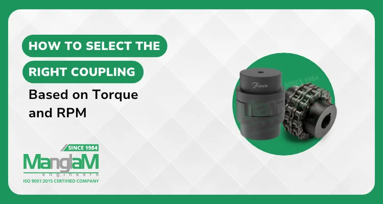
How to Select the Right Coupling Based on Torque and RPM
A coupling can fit both shaft bores and still be the wrong coupling for the drive. Torque determines whether the coupling can carry the transmitted load, while RPM affects the torque calculation, permissible coupling speed and dynamic behavior such as imbalance and vibration.
This guide explains coupling selection based on torque and RPM: how to calculate nominal running torque, apply the manufacturer’s service-factor method, check speed and transient conditions, and match the result to a suitable coupling family. It is written for pump OEMs, maintenance teams, design engineers and procurement teams.
Key Takeaways
- Use Power and Speed at the Coupling: Calculate torque using the transmitted power and RPM at the shaft where the coupling is actually installed, especially when a gearbox changes speed between the motor and coupling.
- Torque Comes From Power and Speed: Nominal running torque in Nm is approximately 9550 multiplied by power in kW, divided by RPM.
- Lower RPM Means Higher Torque at the Same Power: A 7.5 kW drive at 960 RPM transmits about 50% more torque than the same power at 1,440 RPM.
- Follow the Manufacturer’s Service-Factor Method: Do not apply startup, shock or transient allowances twice. Use the selection method specified for the coupling family.
- Check Speed as Well as Torque: The selected coupling size must remain within its published permissible speed at the actual operating RPM.
- Bore Alone Does Not Size a Coupling: A hub may physically fit the shaft and still be undersized for torque, speed or duty.
- Match the Coupling Family to the Duty: Jaw, pin bush, tyre, spacer and geared couplings respond differently to shock, misalignment, maintenance access and environment.
- Verify the Final Model: Confirm torque, speed, bore, movement limits, DBSE and environment against current product data before ordering.
How Do You Calculate Torque From Power and RPM?
Torque (Nm) ≈ 9550 × Power (kW) ÷ Speed (RPM)
This gives the nominal running torque at the coupling location. If the coupling is mounted directly on an electric motor, motor power and operating RPM are usually the starting inputs. If a gearbox or another speed-changing device sits between the motor and coupling, use the transmitted power and rotational speed at the shaft where the coupling is installed.
If the motor rating is given in horsepower, convert it using the applicable nameplate unit. Mechanical horsepower is approximately 0.746 kW per hp. For selection, use the transmitted power at the coupling location where it is known rather than automatically assuming that every point in the drivetrain sees motor-shaft RPM.
For a fixed power, torque rises as speed falls. That is why slower drives such as conveyors, mixers and crushers can impose higher torque on a coupling than faster machines of similar power.
Why Does RPM Change the Coupling You Need?
RPM matters in two separate ways. First, it changes the nominal torque for a given power. A 7.5 kW drive at 1,440 RPM produces about 49.7 Nm, while 7.5 kW at 960 RPM produces about 74.6 Nm.
Second, speed affects the coupling itself. Centrifugal effects, balance and vibration become more important as RPM rises, so every selected coupling size must be checked against its permissible operating speed and any product-specific restrictions.
Manglam Engineers’ Jaw Coupling page publishes torque together with an equivalent kW rating at 100 RPM. Use the published torque capacity for preliminary comparison, then independently verify permissible speed, bore capacity and any other model-specific operating limits before final selection.
What Is Design Torque and How Does a Service Factor Work?
A common coupling-selection method starts with nominal running torque and multiplies it by a manufacturer-specified service factor to obtain a selection or design torque. The factor may account for the driven machine, operating hours, starts, shock, cyclic duty or other application severity, depending on the manufacturer’s method.
As an illustration only, if the applicable selection method uses a service factor of 1.5, the 960 RPM example above would give about 111.9 Nm of design torque (74.6 × 1.5). The factor itself must come from the applicable coupling data, design standard or manufacturer guidance.
Known startup, braking, reversing, jam or transient torque also needs attention. Where the coupling manufacturer publishes separate maximum, startup or transient torque ratings, check those conditions independently. Do not automatically add another allowance if the service-factor method already includes the same load severity.
Selecting a Coupling for a Motor or Pump?
Share the transmitted power, coupling RPM, shaft diameters and operating duty so the application can be reviewed against the appropriate coupling data.
Request a Free QuoteWhich Factors Should You Check Besides Torque and RPM?
Torque and RPM narrow the options, but the final selection depends on the complete drive arrangement.
| Selection Factor | Why It Matters | What to Check |
| Running torque | Sets the baseline transmitted load | Power and RPM at the coupling location |
| Service factor | Accounts for application severity using the selected manufacturer method | Driven equipment, starts, shock, duty cycle and operating hours |
| Transient / peak torque | Checks exceptional loads where separately specified | Starting method, braking, blockage risk, reversing and known torque peaks |
| Permissible speed | Ensures the selected size can operate safely at the required RPM | Selected model against actual operating speed |
| Bore and keyway | Ensures the hub can be mounted correctly on each shaft | Both shaft diameters and shaft connection details |
| Misalignment and axial movement | Affects coupling reaction loads and component life | Angular and parallel misalignment limits, plus permissible axial displacement or end float |
| DBSE and space | Determines physical fit and serviceability for spacer arrangements | Distance between shaft ends, envelope and maintenance access |
A flexible coupling accommodates limited misalignment, but it does not replace proper shaft alignment. Permissible angular and parallel misalignment, axial movement and combined operating limits depend on the coupling design, size and speed, so verify them for the selected model.
Which Coupling Type Suits Your Torque and RPM Profile?
The right family depends on how the drive loads the coupling, how much movement must be accommodated, the environment and how the equipment will be maintained. The examples below link to current Manglam product pages; final model ratings should still be verified before selection.
| Coupling | How It Transmits Torque | Typical Fit | Key Selection Check |
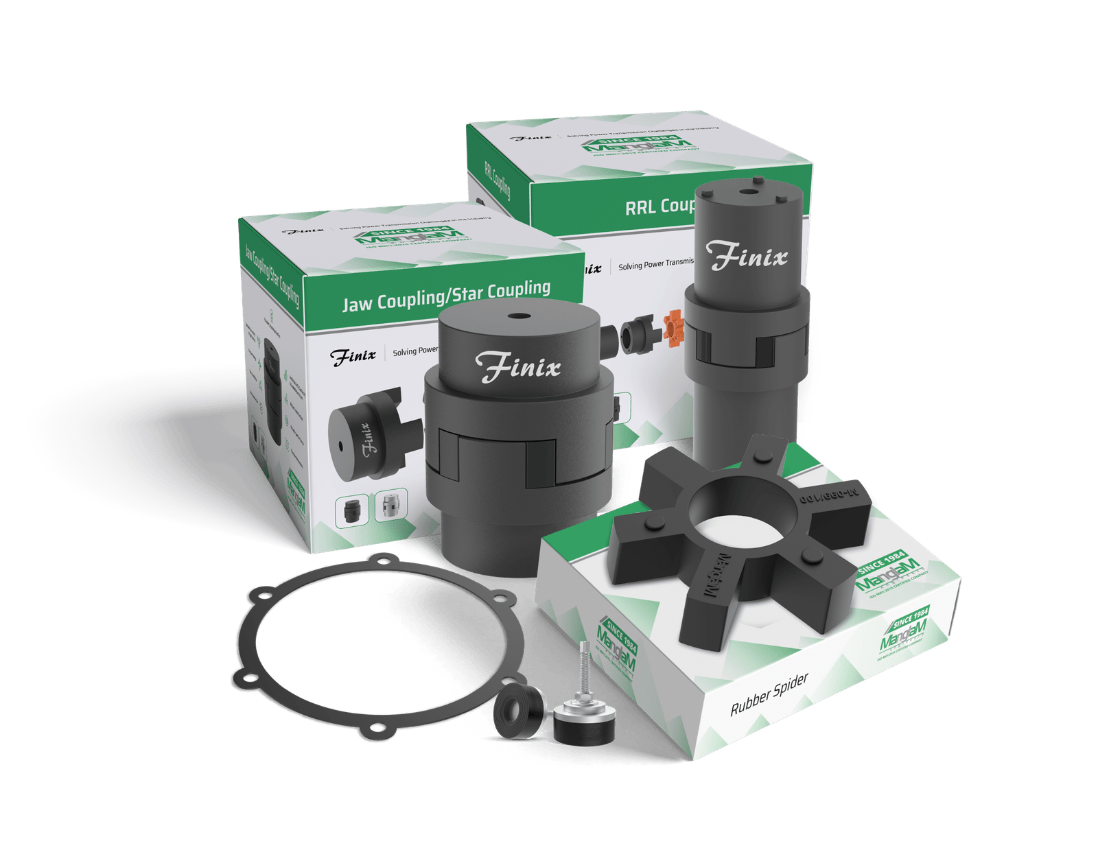
| Jaw Coupling | Elastomeric spider compressed between two hubs | Pumps, motors, gearboxes and general machinery | Coupling size, bore, permissible speed and spider suitability for the application |
| Pin Bush Type Coupling | Pins transmit torque through flexible bushes | Drives with shock and vibration | Model sizing, bore and bush condition / suitability |
| Tyre Coupling | Flexible tyre between two flanges | Applications needing high flexibility and shock absorption | Selected model, tyre configuration, torque and speed limits |
| RRL Coupling | Spacer-style flexible coupling with removable spacer access | Pump and drive layouts needing service clearance | DBSE and a client-confirmed model / datasheet because current RRL page nomenclature is inconsistent |
| MT Coupling | Steel geared construction with internal teeth | Heavy mechanical drives where the published MT design fits | Torque, speed, bore and product-specific maintenance guidance |
Where the flexible element is a wearing component, material selection matters as much as size. Replacement elements such as the Rubber Spider should be selected for the coupling and operating environment rather than matched by diameter alone.
For spacer couplings, DBSE (distance between shaft ends) must match the actual installation and maintenance requirement. Do not transfer torque, speed, bore or dimensional values from one coupling family to another, even when the products appear similar.
Need Help Narrowing the Coupling Family?
Send the power, coupling RPM, shaft sizes, duty and installation constraints so Manglam Engineers can compare the requirement with the appropriate published product data.
Discuss Your Coupling RequirementWhat Are the Most Common Torque and RPM Selection Mistakes?
- Sizing by bore only: The shaft fits, but the coupling may be undersized for torque, speed or duty.
- Using the wrong RPM: Motor RPM is used even though a gearbox changes speed before the coupling location.
- Double-counting load severity: A service factor is applied and the same startup or shock allowance is added again without checking the manufacturer method.
- Skipping the speed check: A coupling size is selected on torque but exceeds its permissible operating RPM.
- Expecting the coupling to fix alignment: Flexible couplings only accommodate limited residual misalignment; correct machine alignment is still required.
- Ignoring the environment: Heat, oil, water or chemicals can affect flexible-element suitability and life.
What Information Does Manglam Need to Confirm a Coupling?
A complete technical request allows the coupling to be checked against the actual drivetrain instead of being selected from bore size alone. Send as many of these details as possible:
- Driver and driven equipment, for example motor and centrifugal pump
- Transmitted power and operating RPM at the coupling location
- Shaft diameters, keyways and connection details
- Nominal, startup or peak torque if already known
- Starting method, shock, reversing duty and operating hours
- Expected angular and parallel misalignment, axial movement or thermal growth where relevant
- Required DBSE or installation envelope
- Operating temperature and exposure to oil, water, chemicals or dust
- Existing coupling model, drawing or dimensional reference for replacement applications
Why Manglam Engineers?
Manglam Engineers is an Ahmedabad-based manufacturer of transmission couplings and industrial rubber parts. Its current website states 40+ years of experience and ISO 9001:2015 certification. The live product range includes multiple flexible, spacer and geared coupling families alongside replacement rubber components.
Manglam also describes tailored product development based on customer requirements. Buyers across the industries Manglam serves, including pump, HVAC, textile and industrial-equipment applications, can use the same technical inputs in this guide when preparing an OEM, replacement or export enquiry.
Conclusion
Selecting a coupling based on torque and RPM is a sequence, not a single calculation. Use power and speed at the coupling location to determine nominal running torque, follow the manufacturer’s service-factor method, check any separately specified transient torque and permissible speed, then confirm bore, alignment, axial movement, DBSE and environment. The final model should always be verified against current product data.
Ready to Confirm the Final Coupling Selection?
Share your drivetrain details with Manglam Engineers so the coupling family and model can be checked against the actual application before ordering.
Get in TouchFrequently Asked Questions
1. How do you calculate coupling torque from kW and RPM?
Use nominal torque in Nm ≈ 9550 × transmitted power in kW ÷ coupling speed in RPM. Use the power and speed at the coupling location, not automatically the motor-shaft RPM if a gearbox changes speed before the coupling.
2. What is a service factor in coupling selection?
A service factor is a multiplier used by a coupling manufacturer or design method to account for application severity. It may reflect driven-machine characteristics, shock, starts, operating hours or other duty factors, so use the factor and method specified for the coupling being selected.
3. Does a higher RPM mean I need a bigger coupling?
Not necessarily. For the same power, higher RPM reduces nominal torque, but the coupling must still remain within its permissible speed. Check both torque capacity and the operating-speed limit of the selected size.
4. Can I select a coupling from motor power alone?
No. Power without RPM cannot establish torque, and a reliable selection also needs shaft sizes, duty, speed, alignment conditions and other installation requirements. If a gearbox is present, use the operating conditions at the actual coupling location.
5. What happens if a coupling is undersized for the torque?
An undersized coupling can overload the elastomer, hubs, teeth, keys, fasteners or other torque-transmitting components, depending on its design. Repeated overload can accelerate wear, deformation or mechanical failure.
6. Can Manglam Engineers supply a coupling for a non-standard requirement?
Manglam Engineers describes tailored product development on its website. Share the shaft sizes, transmitted torque or power, operating speed, duty and installation requirements so the team can confirm what is feasible.