HRC Coupling Selection Guide: Working Principle, Types, Applications & Benefits
September 16, 2026 Dhaval Jani
on

Dhaval Jani
Managing Director at Manglam Engineers
Dhaval Jani is the Managing Director of Manglam Engineers , a trusted manufacturer of transmission couplings and rubber parts. With a background in mechanical engineering and extensive industry experience, he leads the company’s focus on product innovation, manufacturing excellence, and global business growth.
A pump coupling can fit both shaft bores and still be the wrong coupling for the pump. Startup torque, speed, shock load, alignment requirements, and the space needed to service the pump all influence whether the drive runs reliably or creates extra loading on bearings and mechanical seals.
This guide explains the main pump coupling types, where each one fits on industrial pumps, and the inputs you need before choosing. It is written for pump OEMs, maintenance teams, and purchase engineers comparing flexible coupling options for motor-driven pumps.
Key Takeaways
- Match the Coupling to the Pump Arrangement: Close-coupled pumps typically do not use a separate flexible coupling, while separately coupled pumps require a shaft connection selected around torque, alignment, layout, and service access.
- Size for Torque, Not Bore Alone: A hub that fits the shaft may still be undersized for running torque, startup or transient loads, or the application duty.
- Flexible Does Not Mean Alignment-Free: A flexible coupling accommodates limited misalignment within its design limits, but excess misalignment increases reaction forces and can accelerate wear in coupling elements, bearings, and seals.
- Elastomeric Couplings Can Damp Shock and Vibration: Jaw, pin bush, tyre, and wrap-around designs use flexible elements that can cushion shock and damp part of the transmitted vibration, subject to the specific design and element material.
- Spacer Couplings Improve Service Access: A removable spacer can provide the clearance needed for seal or pump maintenance without repositioning the motor when the pump layout is designed for back-pull-out service.
- Choose the Flexible Element for the Environment: Temperature, oil, water, chemical exposure, and the manufacturer’s material limits should be checked before selecting an elastomeric element.
- Confirm Ratings Against the Datasheet: Torque, speed, bore, DBSE, and permissible movement are model-specific, so verify the selected size before ordering.
What Does a Pump Coupling Do?
A pump coupling joins the driver shaft to the pump shaft so torque can be transmitted to the pump. A flexible coupling can also accommodate limited angular and parallel misalignment and, depending on the design, expected axial movement. Elastomeric couplings can additionally absorb shock and damp part of the vibration transmitted between the driver and pump.
Excessive coupling misalignment can create reaction forces and vibration that increase loading on pump and motor bearings and may contribute to mechanical-seal problems. Coupling selection is therefore a reliability decision, not only a connection decision.
What Are the Main Pump Coupling Types?
Start by separating the pump arrangement from the coupling family. A close-coupled pump integrates the motor and pump through a common or rigidly connected shaft arrangement and normally does not use a separate flexible coupling. A separately coupled pump has independent driver and pump shafts connected by a coupling.
For separately coupled pumps, the main coupling families include:
- Rigid couplings: Provide a positive shaft connection with essentially no allowance for misalignment. They are used only where the machine arrangement and alignment requirements support a rigid connection.
- Elastomeric couplings: Use a rubber, polyurethane, or other elastomeric element to transmit torque while providing torsional flexibility and shock or vibration damping. Many designs require no lubrication.
- Gear couplings: Use toothed hubs and a mating sleeve. Metal gear couplings can transmit high torque but generally require lubrication, while nylon-sleeve gear couplings are commonly used for lighter-duty applications and typically do not require lubrication.
- Disc couplings: Use flexible metallic disc packs to accommodate limited misalignment while transmitting torque with high torsional stiffness and little damping.
- Diaphragm couplings: Use one or more thin metallic diaphragms that flex to accommodate movement. They are distinct from disc-pack couplings and are generally selected where high speed, torsional stiffness, and low maintenance are important.
Pump Coupling Types Compared
| Coupling Type | How It Works | Best Suited For | Maintenance Point | Key Selection Risk |
| Jaw (star) | Two hubs compress an elastomeric spider | General motor-to-pump drives where ratings and environment suit | Inspect the spider for wear | Spider compatibility with duty, temperature, and media |
| Pin bush | Steel pins transmit torque through flexible rubber or PU bushes | Drives where shock cushioning and serviceable bushes are useful | Bushes can be checked and changed | Excess misalignment or incorrect sizing can accelerate bush wear |
| Tyre | Flexible rubber-fabric tyre between flanges | Applications needing high flexibility, shock absorption, or greater misalignment accommodation | Split tyre can be replaced radially on suitable designs | Confirm torsional behavior, permissible misalignment, and selected size ratings |
| Snap Wrap (SW) | Wrap-around elastomer element between hubs | Pumps needing easy radial access to the flexible element | Element can be inspected or replaced radially where the design supports it | Confirm element compatibility and whether spacer access is required |
| RRL spacer | Flexible coupling arrangement with a removable spacer | Compatible pump layouts needing maintenance clearance around the shaft ends | Spacer can be removed for service where the installation permits | Confirm actual DBSE, maintenance clearance, and current model data |
| Nylon gear | Steel gear hubs with a nylon sleeve | Light to medium duty pump systems where the model ratings fit | Typically no lubrication required | Verify torque, speed, bore, and movement limits for the selected model |
Where Does Each Coupling Fit on a Pump?
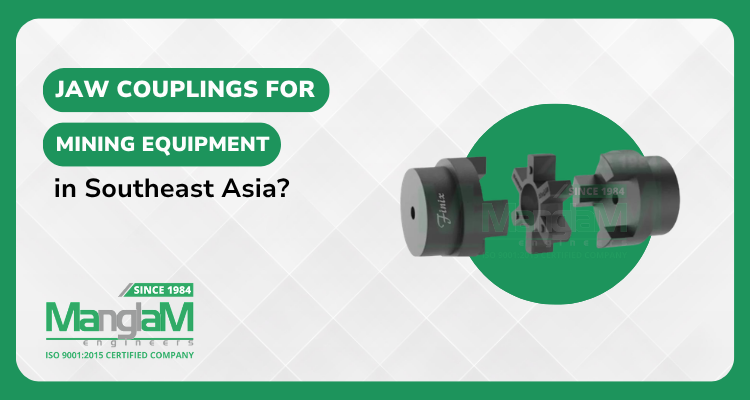
Jaw Coupling: Two hubs and an elastomeric spider transmit torque, provide torsional flexibility, and accommodate limited shaft misalignment. It is a common option for motor-to-pump drives when its torque, speed, bore, and spider requirements suit the duty.
Pin Bush Type Coupling: Steel pins with rubber or polyurethane bushes cushion shock and vibration. Manglam’s current product page states that the bushes can be checked and changed without moving connected machines, which can simplify maintenance.
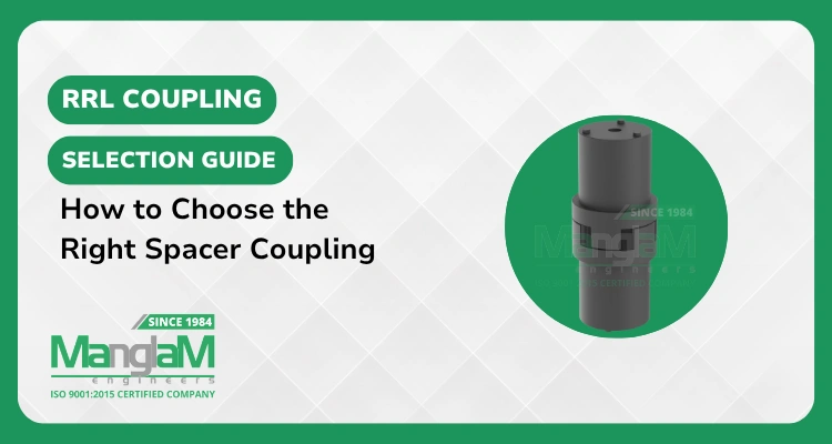
RRL Coupling: A spacer-style flexible coupling for layouts that require a defined distance between shaft ends. In a compatible back-pull-out pump arrangement, removing the spacer can provide the clearance needed for seal or pump maintenance without repositioning the motor.
SW Coupling: A wrap-around elastomer design that allows radial inspection or replacement of the flexible element. Manglam’s current SW Coupling page also references an optional spacer, so it can be considered where radial element access is important.
Tyre Coupling: A highly flexible rubber-fabric tyre between two flanges. Consider it where shock absorption, torsional flexibility, or greater misalignment accommodation is required, then verify the selected model against the actual pump duty.
Nylon Gear Coupling: Two steel gear hubs and a nylon sleeve provide a compact, lubrication-free connection for light to medium duty applications, including pump systems, when the torque, speed, bore, and movement limits are suitable.
Need Help Choosing the Right Pump Coupling?
Share your pump type, motor power, RPM, shaft sizes, operating duty, and maintenance-access requirements with Manglam Engineers for application-based guidance.
Discuss Your Coupling Requirement →How Do You Select a Pump Coupling?
Start with the driver and pump arrangement, then size the coupling around torque, speed, shaft connection, alignment requirements, service access, and the operating environment. Do not select a coupling from shaft bore alone.
- Identify the driver, pump type, and operating arrangement.
- Calculate nominal running torque from motor power and operating RPM.
- Apply the coupling manufacturer’s appropriate service factor for the actual driver, driven equipment, and operating duty to determine design torque.
- Check startup, transient, reversing, or other peak torque separately against the coupling’s permissible transient or maximum rating where applicable.
- Confirm both shaft diameters, keyways, and other shaft-connection requirements.
- Confirm angular and parallel alignment requirements, plus expected axial displacement or end float, including movement caused by thermal growth.
- For a spacer coupling, confirm the required DBSE from the actual shaft-end positions, pump layout, and maintenance-clearance requirement.
- Check the environment, including temperature, oil, water, chemicals, dust, and other exposure that can affect the flexible element or coupling components.
- Verify rated torque, maximum speed, bore capacity, dimensional envelope, and permissible movement against the selected model’s current datasheet.
Selection limits belong to each model, so never carry a torque, speed, bore, DBSE, or misalignment rating from one coupling family to another.
Have Your Pump Coupling Selection Inputs Ready?
Send the motor power, RPM, shaft diameters, keyways, required DBSE, and operating duty so the coupling can be checked against the actual application before ordering.
Request a Free Quote →Why Do Pump Couplings Fail Early?
Early coupling problems often point to a sizing, alignment, installation, or environment mismatch. The symptom can guide inspection, but it should not be treated as a complete root-cause diagnosis.
| Symptom | Possible Cause | Inspection Step |
| Cracked, hardened, or swollen elastomer | Temperature, media exposure, aging, or incorrect element material | Compare actual operating conditions with the approved element material and inspect the complete coupling |
| Rapid element or bush wear | Misalignment beyond the selected model limits, excessive movement, or incorrect sizing | Re-check shaft alignment and compare the application with the model limits |
| Vibration or noise | Worn element, loose fasteners, alignment error, unbalance, or unsuitable coupling selection | Inspect the element and fasteners, check alignment, and re-verify torque and speed requirements |
| Mechanical-seal leakage | Possible shaft movement, vibration, alignment, bearing, piping-strain, or seal-related problem | Check alignment and rotating-equipment condition as part of the diagnosis rather than replacing the seal alone |
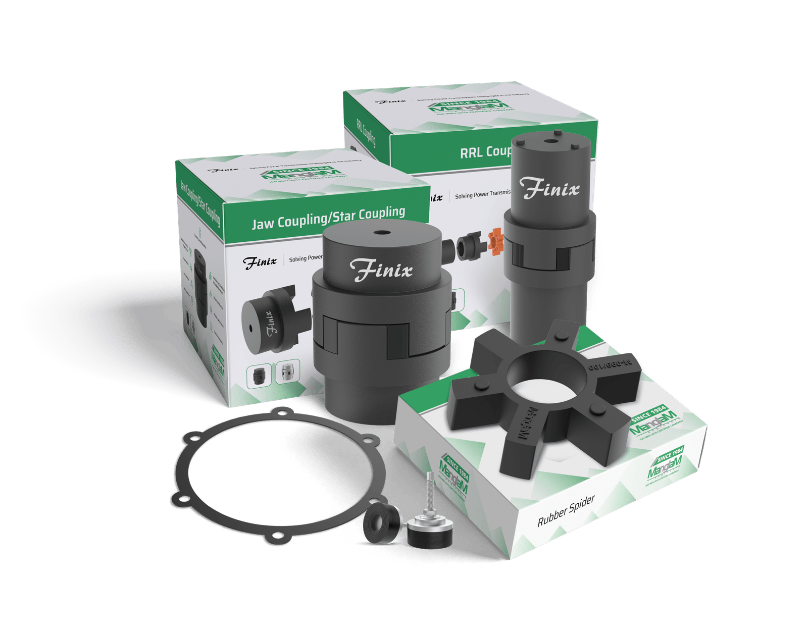
When replacing a worn jaw-coupling element, confirm the current application conditions rather than matching only the old part. Manglam’s Rubber Spider page provides the current product reference for jaw-type replacement spiders.
Why Manglam Engineers?
Manglam Engineers manufactures mechanical power transmission couplings and industrial rubber parts from Ahmedabad, Gujarat. Its current coupling range includes jaw, pin bush, RRL spacer, SW, tyre, nylon gear, and other coupling families, while its Industries page lists pump manufacturers among the industries served. For a technical enquiry, matching the coupling to the actual application inputs is more useful than selecting from bore size or coupling name alone.
Conclusion
The right pump coupling follows from a sequence of checks: pump arrangement, running and design torque, speed, shaft connection, alignment requirements, service access, DBSE where applicable, and the operating environment. These inputs usually narrow the choice to one or two suitable coupling families, after which the exact size should be confirmed against the current model datasheet.
Need a Pump Coupling Checked Before You Order?
Share your motor power, RPM, shaft sizes, DBSE where applicable, duty, and operating conditions with Manglam Engineers to confirm the suitable coupling type and current model specifications.
Get in Touch →FAQs
1. What is the most common coupling for a centrifugal pump?
A flexible coupling is commonly used on horizontal, separately coupled centrifugal pumps. Elastomeric jaw and spacer-type couplings are common options, but the final choice depends on torque, speed, shaft size, alignment requirements, service access, and the operating environment.
2. Can a flexible coupling correct poor shaft alignment?
No. A flexible coupling accommodates limited misalignment within its model-specific limits, but it is not a substitute for correct shaft alignment. Excessive misalignment increases coupling reaction forces and can accelerate wear in coupling elements, bearings, and seals.
3. What is DBSE in a pump coupling?
DBSE means Distance Between Shaft Ends. In a spacer-coupled pump train, it is a key installation dimension used to determine the required spacer arrangement, while the actual maintenance clearance also depends on the removable spacer and connected equipment design.
4. Do pump couplings need lubrication?
Many elastomeric couplings, including common jaw, pin bush, tyre, and wrap-around designs, do not require lubrication. Metal gear couplings generally do, while nylon-sleeve gear couplings are commonly self-lubricating. Always confirm the requirement for the specific model.
5. When should a coupling spider be replaced?
Replace or investigate the spider when inspection shows cracking, hardening, swelling, deformation, or excessive wear, or when operating symptoms indicate deterioration. Confirm that the replacement material and size suit the current duty and environment rather than matching only the old part.
6. What information is needed to quote a pump coupling?
Send the driver and pump type, motor power, operating RPM, shaft diameters, keyways, required DBSE where applicable, duty conditions, alignment or movement requirements, and the operating environment. An existing coupling model number or drawing is also useful for replacement applications.